
AC/DC jokes aside, this is important current information.
So, by now, I assume you have read the previous post, Electricity: Part 1, at least five or six times to really grasp the intricacies of what electricity is and how it relates to the transfer of energy. You may also have read it once, fallen asleep and Google led you back here to part two against your will. Either way, I hope you enjoy the following discussion on the topics of electrical loads, alternating vs. direct current, single phase vs. three phase power, and the generation of electrical energy. Please enjoy it, I’ve lost a lot of sleep working on it. Sorry; that was supposed to be an inner monologue comment.
At this time, I’d like to ask for patience from those who are not big fans of geometry, trigonometry or other forms of mathematics. I’ll try and keep some of these concepts as simple as possible, while trying not to offend the majority of engineers, mathematicians or academics by being partially or even totally wrong. I will also try and keep the electrical jokes to a minimum. This subject is not for everyone so I make no promises.
Circuits
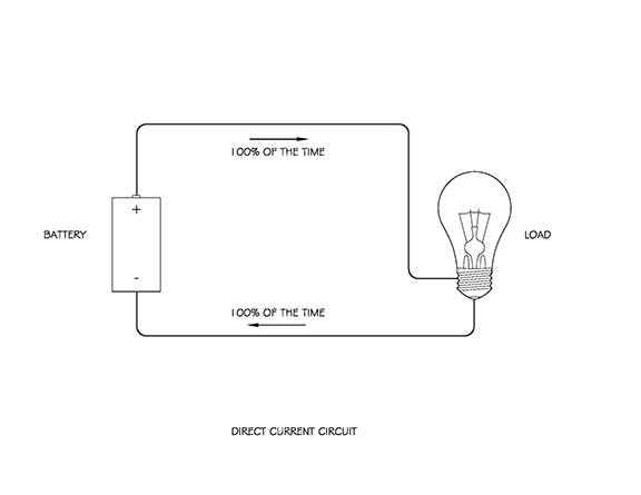
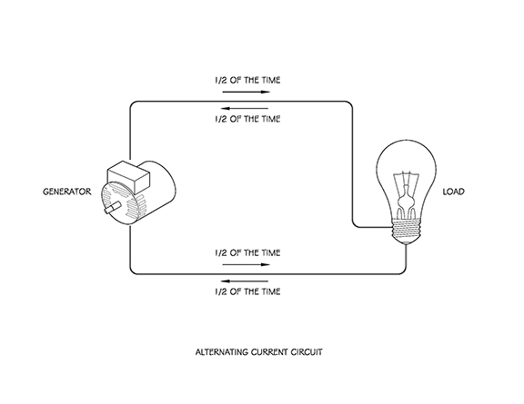
In Part One, I introduced the idea of an electrical circuit. Electrons and the electromagnetic energy they carry will not flow from one pole to another unless their path is fully connected. Flipping a switch in your home either breaks the circuit (literally creates a gap in the wiring), or completes an electrical circuit and allows the flow of electrons. The following images show the simplest of circuits; one with a battery (a power source), wiring (path) and a light bulb, where the flow of current travels from one terminal of the battery, through the wire into the light bulb, causes the bulb’s filament to glow brightly and then continues on through the wiring to the battery’s opposite terminal. The second image is similar to the first, but the power source in this case is an AC Generator, so the flow of electrons change directions at a certain frequency. We will get into the differences between AC and DC later in the discussion.
Every electrical circuit needs both a power source and something to resist the flow of electrons. Without some resistance, electrons will flow very quickly through a conductor. Given no speed limit (and no fear), drivers on an interstate would drive as fast as they can. If everyone drove like they were qualifying for the Daytona 500, you can imagine how many accidents would occur and the entire transportation system would break down. Electrical current is no different. If permitted, electrons will move as fast as possible in larger numbers and would eventually exceed the wire’s ability to handle the heat generated by the flowing electrons. When this happens, the wire can actually melt or catch its insulation on fire. A common cause for this type of excessive current is a “short circuit” where someone directly connects the two poles of a battery, or when a current carrying conductor (wire) comes in contact with metal objects or people; allowing current to flow unimpeded into them or into the ground. Resistance keeps the flow of electrons in check. For any normally operating circuit, this is not a problem since the entire point of electricity is to supply energy to some kind of device or equipment. The component of a circuit that utilizes the energy being transported and provides some resistance is known as a load.
Loads can be categorized into many different groups, but the most common are resistive, capacitive, and inductive. I know, the terms are beginning to sound complex and you may have started dozing off, but think of them as loads that resist the flow, capture the flow, or induce their own flow of electrons. It’s an over-simplification, but it works for me.
Types of Loads
Resistive
Resistive loads are some of the most commonly known (or thought of), and are characterized by the fact they create heat (and/or light), the voltage and current are in phase with each other (more on phase later), and they do not generate their own magnetic field. Common resistive loads would include incandescent light bulbs and most electric heaters.
Resistive loads take advantage of the fact that some metals are conductive, but put up a fuss when they are energized. Much like a teenager when they are asked to clean their room; they are fully capable of doing so, but they sure put up a lot of resistance to do so, and cause their parents tempers to rise. I know it’s a thin comparison, but as a parent, its painfully relevant.
Certain elements such as Tungsten, used in common incandescent light bulb filaments, and an alloy used in heating elements called Ni-chrome (a mixture of Nickel and Chromium), are conductive, but when electrical current is passed through them, they emit much of the energy as either light, heat or both. Given the fact that only one of these results is typically desired, the balance of the energy used is wasted. This makes resistive loads very simple, but also very inefficient.
Capacitive
Devices used as capacitive loads are commonly referred to as capacitors. I know; big shock (the puns don’t stop here folks). Capacitors are capable of storing an electrical charge that can be released at a desired speed and quantity. Capacitors are not unlike a short-term rechargeable battery, but are used to store a large charge that can be released nearly all at once, or released slowly to provide a more even voltage or current. Although used in nearly every electronic device made today that can plug into an outlet, some better-known examples of devices that heavily rely on capacitors would be camera flash-bulbs, defibrillators and joy buzzers (although the last item is not a very safe or nice use of a capacitor, and no I’m not suppressing painful childhood experiences).
Inductive
Inductive loads can seem more complex, but are one of the essential reasons humans learned how to harness the power of electricity.
As discussed in Part 1 of this post, we learned that passing electrical current through a conductive material creates a magnetic field. In single conductors the field is negligible, but when current is passed through a coil made of some conductive material, a larger magnetic field is created. The exact opposite is also true. If a coil of wire is passed through a magnetic field, it introduces a flow of current in the coil / conductor. Simply put; pass a magnet by a coil you get current in the coil. Energize a coil and you get a magnetic field.
This behavior of inductance is the reason that generators are able to create a flow of electricity and why motors are able to transform electrical energy into mechanical movement. The discussion of inductance is a substantial one on its own, and we could spend hours talking about induced voltage, power factors, and other engineering type stuff, but I’m stopping here. I don’t have the capacitance to go on, so I’m going to focus on how inductance allows for the creation of electricity as we use it in residential and commercial buildings across the world.
I’m a fan of AC/DC, and it’s not just a phase.
Let’s talk about AC, DC, Edison and Tesla (the man, not the car manufacturer).
Thank you to Maggie Ryan Sandford at mentalfloss.com for the following information, and lets be honest; most of the words.
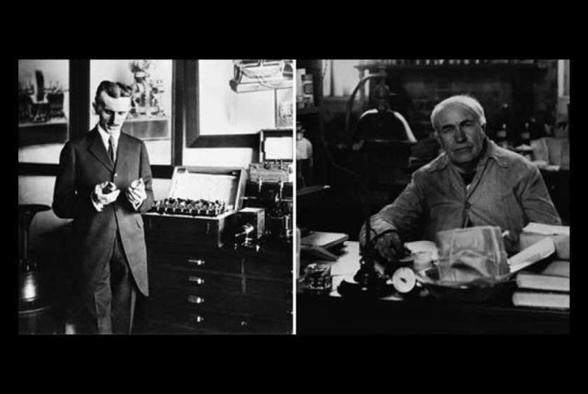
For those geeks like myself that enjoy a bit of scientific history and trivia, this may not be new information, but to everyone else, the story of Alternating Current (AC), Direct Current (DC), Thomas Edison, Nikola Tesla and Niagara Falls sounds like a made-for-TV movie.
Nikola Tesla, a Serbian by parentage, began working for the Continental Edison Company in Paris in 1882. After gaining praise from his supervisor, he was invited to the US to work alongside Thomas Edison himself. Although Edison thought the man’s ideas were “splendid”, he found them “utterly impractical”. Edison and Tesla both worked long hours, were egocentrics and required little sleep (don’t they sound like a lot of fun to be around… wait, that sounds a lot like me… never mind). Their contrasting work and personal styles, mixed with what seems like sleep deprivation, led to many long, grumpy hours in the workshop.
Edison’s least favorite idea of Tesla’s was the concept of using alternating current technology to bring electricity to the people. Edison was much more partial to his own direct current system, and maintained that the lower voltage from power station to the consumer was safer. AC technology allows for the flow of energy to periodically change direction, and is more practical for transmitting massive quantities of energy over long distances. At the time, DC systems only allowed for a power grid within a one-mile radius of the power source (talk about a case of NIMBY: Not In My BackYard). The conflict between the two technologies, as well as Edison and Tesla’s feud, became known as the War of Currents, hence the not so hidden meaning behind the band name AC/DC.
Tesla eventually sold most of his patents to George Westinghouse (not an unfamiliar name to those familiar with power generation), who built one of the first AC power plants at Niagara Falls to power New York City, and then used the same principles to create much of the modern power grid we have today.
Edison wasn’t wrong however, as the higher voltages of AC are not safe or practical for use in smaller consumer electronics or appliances used in the home; hence the myriad of “power supplies” and converters used in our everyday lives. These converters and power supplies change the higher-voltage alternating current into a lower voltage direct current that can be used more effectively.
So AC and DC technology have been around for quite some time, but what is the difference?
Direct Current
Direct Current (DC) is electrical energy supplied at a constant voltage (approximately). DC is normally used at levels of 24 volts and lower, but can be occasionally seen higher. If plotted on a graph of voltage over time, it may look like the following diagram:
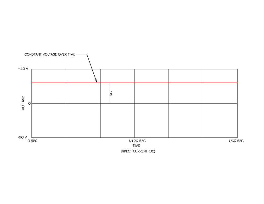
DC is pretty much the standard for point-of-use electrical needs in consumer electronics and anything else that requires very precise and consistent current flow. DC loads can be resistive, capacitive and inductive.
Alternating Current
Most of the electric power in the world is AC. Electricians work with AC about 99% of the time, given its wide use in building electrical systems and its ability to transport energy over long distances. One of the biggest advantages of AC is that is can be transformed and DC cannot. A transformer can step up or step-down voltages as needed for certain devices and depending on what stage of transmission the energy is in. As power always equals the voltage times the amperage, a much larger amount of energy can be transmitted at very high voltages without having to increase the amperage (and therefore wire size). Tesla was a very smart man (if not sometimes foolish; can you imagine what he’d be worth if he hadn’t sold his patents).
Although other methods are available, the most common way of producing AC is by rotating a magnetic field past coils of conductive material, producing an electric current (that whole inductance thing again). The same effect can be created by rotating coils around a stationary magnet. In either case, an electric current is produced in the coil. When the coil is closest to the positive pole of the magnet, the maximum voltage is created in a positive direction. As the magnet is rotated further, the voltage drops increasingly faster until it reaches zero at the time the poles of the magnet are the farthest from the coil. As the magnet continues to rotate, the negative pole gets closer to the coil and the voltage in the coil becomes greater in the negative direction. One complete rotation of the magnet results in one “cycle”, where the voltage starts at zero, reaches its maximum positive value, reaches zero again, reaches its maximum negative value and then returns to zero. The term for cycles per second is called hertz. In the United States, AC is normally provided at 60 Hz (60 cycles per second). Just blew your mind a bit didn’t it? I hope it didn’t hertz too much. Sorry, I couldn’t resistor. I kill me.
The diagram below shows the relationship between a rotating point on a circle and the resulting rising and dropping of the voltage. This resultant form is known as a Sine wave, and is one of the most commonly seen wave-forms in nature. Sine waves are also seen in radio waves and any other machine with rotating motion.
Single Phase vs Three Phase
Those professionals who deal with commercial projects have heard the term “Three-Phase Power” more than once, and even the typical homeowner has heard things like “120/240”. I’m sure those terms scare even electricians sometimes as electricity should just be on or off right? Why all the rocket science?
Amazingly, it’s not really difficult.
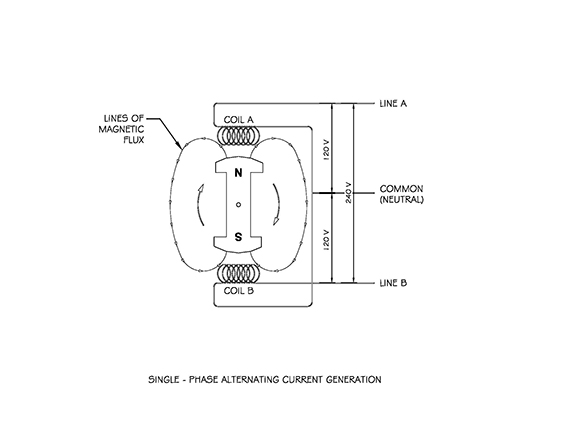
Single phase power is created when you rotate a magnetic field past one or more connected coils. The resulting voltage and current is always “in phase”, and three times every cycle the voltage is zero. If you generate 120 volts of electricity and then add it to 120 volts of electricity in the same phase, you get double the voltage. This is considered “single-phase” power. In typical residential electrical services, the power company brings two conductors that can each carry 120 volts and a neutral. If you connect say a motor to one of the “hot” conductors and the neutral, it will receive 120 volts. If you connect the motor to both hot conductors, you will get twice the voltage: 240V. Refer to the following diagram to see how the coils of a single-phase generator are “tapped” to get 120 or 240 volts.
Three-Phase Power
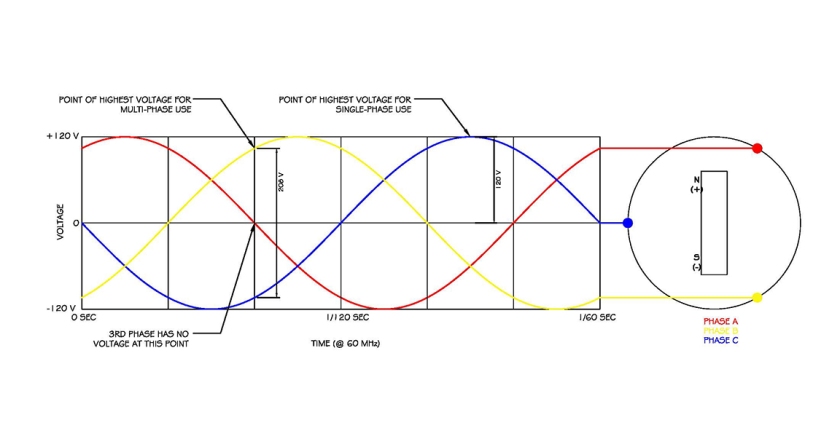
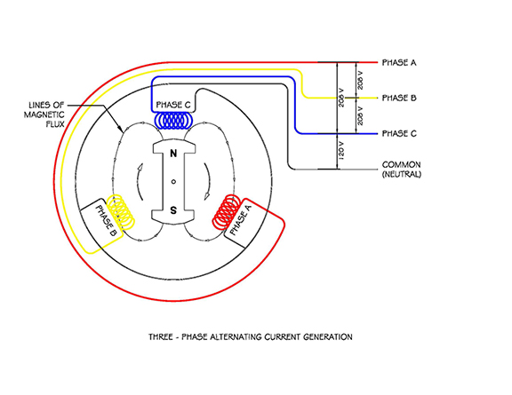
Three-Phase power is created by rotating a magnetic field past coils that are spaced 120 degrees apart from each other. Why should this make a difference?
Refer to the following diagrams for clarification, but you’ll quickly see that by spacing the coils equally apart, the sine waves created are also exactly 120 degrees apart. This means that when two or more of the phases are connected together, the resulting voltage never drops to zero. Because the voltage in each phase is offset at any one point, the maximum voltage between two or three phases is not double the single-phase voltage of 120, instead it is equal to the maximum voltage times the square root of 3 . If the single phase maximum voltage is 120, then the maximum voltage using two or three of the phases is 208V. I could further explain this correlation using vectors and trigonometry, but don’t you think I’ve beaten you up enough at this point?

Why use three-phase power?
Three-phase connected motors are much more efficient with the same power and can be used to run longer and with less overall work. If every phase is providing voltage at some point, the motor is never without power. Newton’s 3rd law of motion: A object in motion tends to stay in motion. Keep it going and it takes less work to move it!
OK, time for a metaphor!!
Let’s say you were pushing a small child around on a merry-go-round (yes, they were a very popular playground element before lawyers got involved). One person standing in place could push on the merry-go-round once every time it went around and keep it moving. It would slightly slow down before each push, but you could keep it going. Now put ten kids on that same merry-go-round and one person pushing seems a bit daunting; But, if you were to position three adults around the merry-go-round and each one pushed every time the same spot came by, they’d be pushing three times as much and the fun would never stop; well at least until some poor child decided they’d held onto their lunch long enough. As I’ve said before; metaphors have their limits.
Three phase power is generally limited to commercial use due to the higher number of conductors, and commonly higher voltages, but is nonetheless very common and much more efficient.
Ok, if you have made it this far, I commend your perseverance (or stubbornness). If you understand everything I’ve talked about; please call and re-explain it to me. I may have dozed off in the middle while typing. For your moment of Zen, please enjoy the following animation of a full three-phase genset I modeled. It shows the parts flying away in fantastic fashion. I will try and elaborate on the various parts of the genset in a later post, but for now, enjoy the model and animation that was way more complicated than necessary.
Thank you.

All graphics and animations in this post, with the exception of the two photos were created by DFD Architects, Inc., ©2018 DFD Architects, Inc. ALL RIGHTS RESERVED. No image, video or animation on this post may be reproduced, transmitted, stored, or used in any form without the prior written permission of DFD Architects, Inc. I’m not kidding.
Gracious Acknowledgements to the following sources for information and selected passages, I couldn’t have written this without their guidance or copying their words:
Delmar’s Standard Textbook of Electricity, Sixth Edition. By Stephen L. Herman. Copyright 2016, Cengage Learning. Kindle Edition.
AC/DC: The Tesla-Edison Feud, by Maggie Ryan Sandford, July 10, 2012. http://www.mentalfloss.com
http://mentalfloss.com/article/30140/acdc-tesla%E2%80%93edison-feud
Thank you especially to my father, John D. Gillen, for passing along just enough of his electrical engineering expertise to make me a geek but remain somewhat socially acceptable.
p.s., I’ll buy a beer for the first (over 21 years of age) person in the State of Texas to correctly identify the location of the facility on the cover image (location name and affiliation). Geeks have to stick together! (Follow up: I’m proud to say my father was the first to get this correct; Extra points to Loyd Dittfurth for also identifying exactly where the image itself came from). For those who still haven’t gotten it; its in a cold and snowy place far far away.
